Intrinsic and Extrinsic Calibration for Around-View Fisheye Cameras
Date:
1. Background
The calibration of camera intrinsic parameters and the calibration of extrinsic parameters for multiple sensors are fundamental to the tasks of localization and mapping. The accuracy of these calibrations also plays a crucial role in the performance of SLAM (Simultaneous Localization and Mapping) systems. Intrinsic calibration includes the estimation of the camera intrinsic matrix, camera model parameters, and distortion model parameters. Once the camera intrinsics are known, it is possible to project 3D points in the camera coordinate system onto the camera’s imaging plane. Extrinsic calibration primarily addresses the problem of calculating the relative poses between multiple sensors, forming the basis for data association, alignment, and registration between the observational data from different sensors.
2. Fisheye Camera Intrinsic Calibration
2.1 Fisheye Camera Model
To ensure compatibility with the AprilTag localization code used in the camera-to-vehicle extrinsic calibration, the OpenCV fisheye model is adopted for the intrinsic calibration of the fisheye camera. For a 3D point \(X_c=(x,y,z)^T\) in the camera coordinate system, let
\[a=\frac{x}{z},\ b=\frac{y}{z}\] \[r=\sqrt{a^2+b^2}\] \[\theta=\arctan(r)\]The fisheye camera image distortion model can be expressed as
\[\theta_d=\theta\left(1+k_1\theta^2+k_2\theta^4+k_3\theta^6+k_4\theta^8\right)\]After distortion, the coordinates of the 3D point on the normalized plane \((x’,y’)^T\) are
\[x'=\left(\frac{\theta_d}{r}\right)a\] \[y'=\left(\frac{\theta_d}{r}\right)b\]Finally, the pixel coordinates \((u,v)^T\) on the fisheye image are
\[u=f_x\left(x'+\alpha y'\right)+c_x\] \[v=f_y y'+c_y\]where \(f_x,f_y,c_x,c_y\) are the camera’s intrinsic parameters.
2.2 Fisheye Camera Intrinsic Calibration
The fisheye camera intrinsic calibration code can be found in the opencv_calibration directory under avm_calibration.
When performing intrinsic calibration, calibration data is first collected for each of the four fisheye cameras separately, as shown in Figures 2.2.1 to 2.2.4. During data collection, the calibration board should be moved in various dimensions as much as possible within the camera’s field of view without leaving the visible area, to cover the entire field of view.
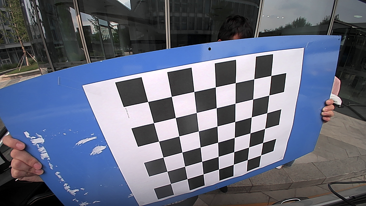
Figure 2.2.1 Calibration image for the right fisheye camera
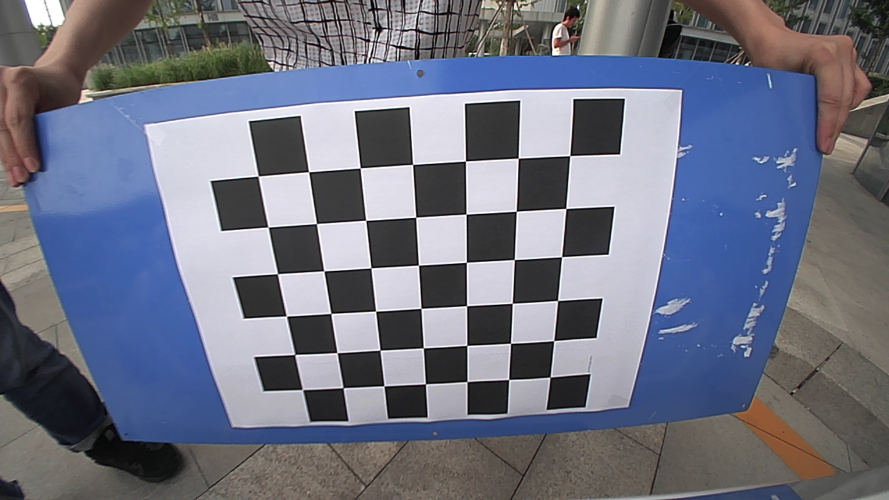
Figure 2.2.2 Calibration image for the front fisheye camera
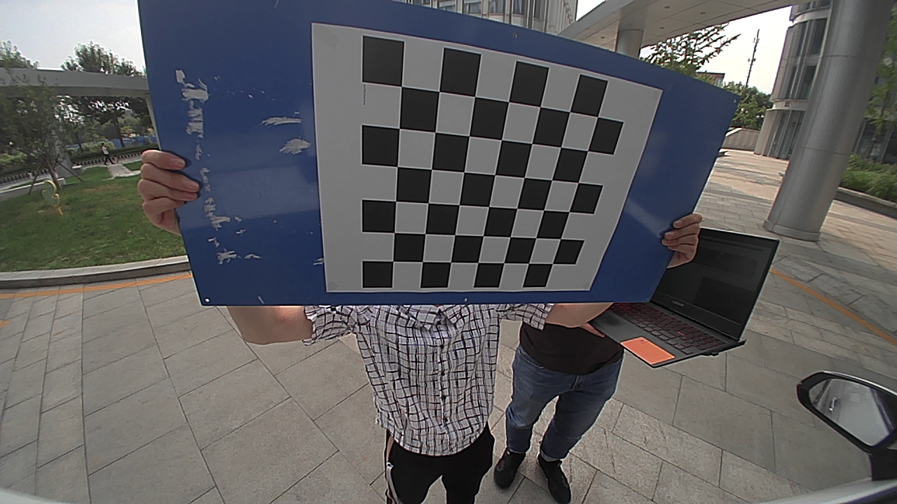
Figure 2.2.3 Calibration image for the left fisheye camera
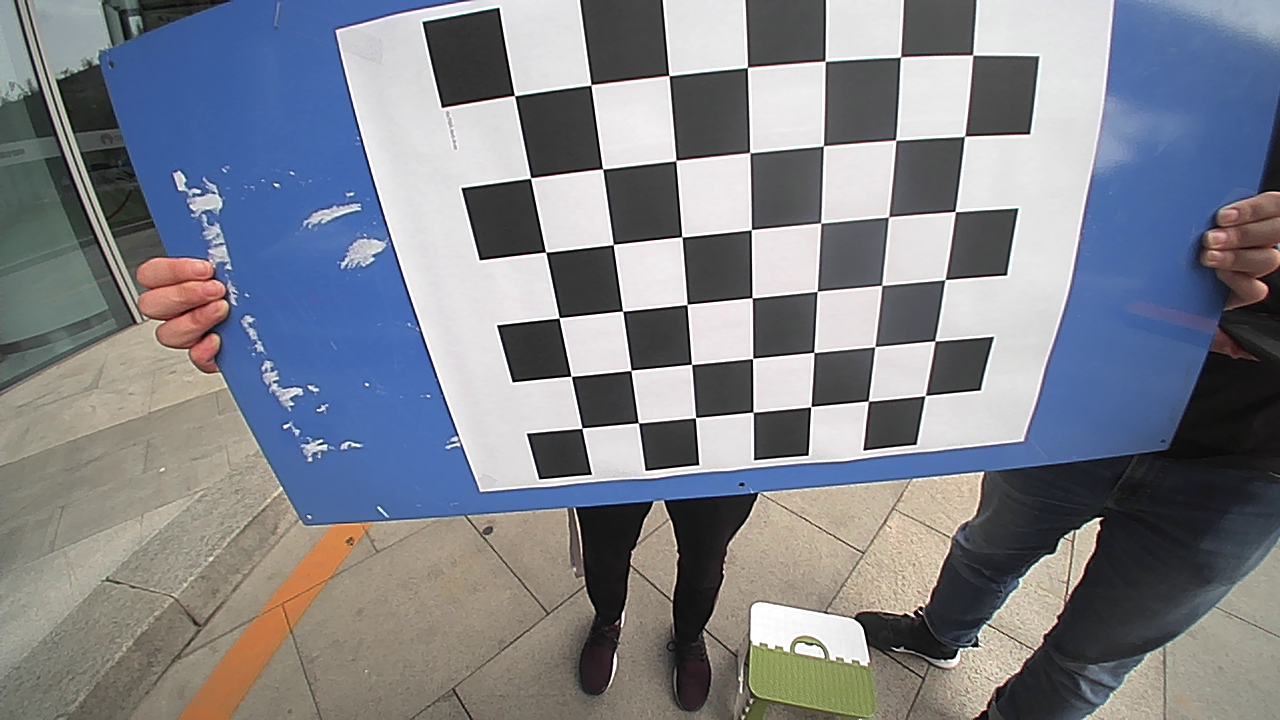
Figure 2.2.4 Calibration image for the rear fisheye camera
After collecting the calibration images, create a folder named img_${camera} in the project directory to store the collected calibration images, and generate a img_${camera}.txt file listing the relative paths of all calibration images. For example, the calibration images for the right camera are stored in the ./img_right directory, with the corresponding ./img_right.txt file content as follows:
# ./img_right.txt
img_right/1631690408.524919.png
img_right/1631690409.663292.png
img_right/1631690410.457858.png
img_right/1631690411.546102.png
img_right/1631690412.438392.png
...
After deploying the calibration images in the aforementioned manner, run run.sh in the project directory (./opencv_calibration) to complete the intrinsic calibration for the four surround view cameras.
# -------
# run.sh
# -------

#!/bin/sh

./calibration img_right.txt calib_right.yaml
./calibration img_front.txt calib_front.yaml
./calibration img_left.txt calib_left.yaml
./calibration img_rear.txt calib_rear.yaml

cp ./calib_right.yaml ../data/img/calib_right.yaml
cp ./calib_front.yaml ../data/img/calib_front.yaml
cp ./calib_left.yaml ../data/img/calib_left.yaml
cp ./calib_rear.yaml ../data/img/calib_rear.yaml
The calibration output is a calib_${camera}.yaml configuration file, which includes the image resolution, camera intrinsic matrix, and distortion model parameters. This file can be directly used for camera-to-vehicle extrinsic calibration. For example, the output configuration file for the right camera contains:
# ----------------
# calib_right.yaml
# ----------------

image_width: 1280
image_height: 720
camera_name: camera
camera_matrix:
  rows: 3
  cols: 3
  data: [429.74459114051712, 0, 619.22596643438362, 0, 429.83803063011919, 401.92878121320769, 0, 0, 1]
distortion_coefficients:
  rows: 1
  cols: 4
  data: [0.29938336892050299, 0.073557008355643466, -0.069200024479249625, 0.010450303044365006]
2.3 Intrinsic Calibration Results
The camera intrinsic matrix and distortion parameters are denoted by
\[K= \begin{bmatrix} f_x & 0 & c_x \\ 0 & f_y & c_y \\ 0 & 0 & 1 \end{bmatrix}\] \[D= \begin{bmatrix} k_1 & k_2 & k_3 & k_4 \end{bmatrix}\]The four surround view cameras are identified with subscripts. The intrinsic calibration results are recorded as follows:
\[K_{right}= \begin{bmatrix} 429.74 & 0 & 619.23 \\ 0 & 429.84 & 401.93 \\ 0 & 0 & 1 \end{bmatrix}\] \[D_{right}= \begin{bmatrix} 0.299 & 0.073 & -0.069 & 0.010 \end{bmatrix}\] \[K_{front}= \begin{bmatrix} 433.16 & 0 & 595.30 \\ 0 & 432.75 & 386.14 \\ 0 & 0 & 1 \end{bmatrix}\] \[D_{front}= \begin{bmatrix} 0.309 & 0.063 & -0.040 & -0.012 \end{bmatrix}\] \[K_{left}= \begin{bmatrix} 431.10 & 0 & 614.08 \\ 0 & 431.83 & 399.31 \\ 0 & 0 & 1 \end{bmatrix}\] \[D_{left}= \begin{bmatrix} 0.304 & 0.116 & -0.136 & 0.043 \end{bmatrix}\] \[K_{rear}= \begin{bmatrix} 431.71 & 0 & 654.41 \\ 0 & 431.32 & 389.04 \\ 0 & 0 & 1 \end{bmatrix}\] \[D_{rear}= \begin{bmatrix} 0.299 & 0.085 & -0.090 & 0.022 \end{bmatrix}\]2.4 Evaluation of Intrinsic Calibration Results
The accuracy of the intrinsic calibration is assessed by calculating the reprojection error, as shown in the table below.
| camera_right | camera_front | camera_left | camera_rear | |
|---|---|---|---|---|
| reprojection error | 0.26px | 0.28px | 0.20px | 0.21px |
3. Camera-to-Vehicle Extrinsic Calibration
3.1 Overview of the Extrinsic Calibration Scheme
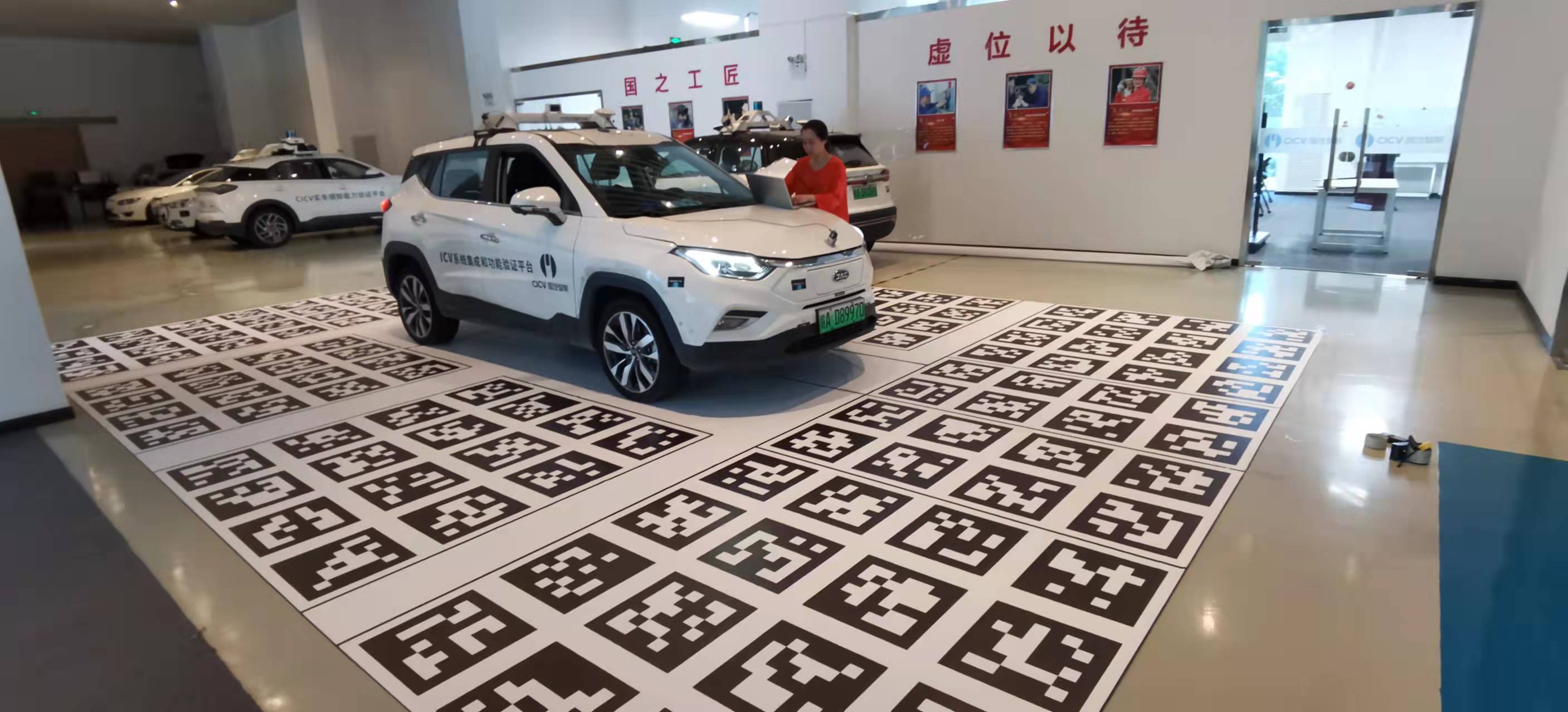
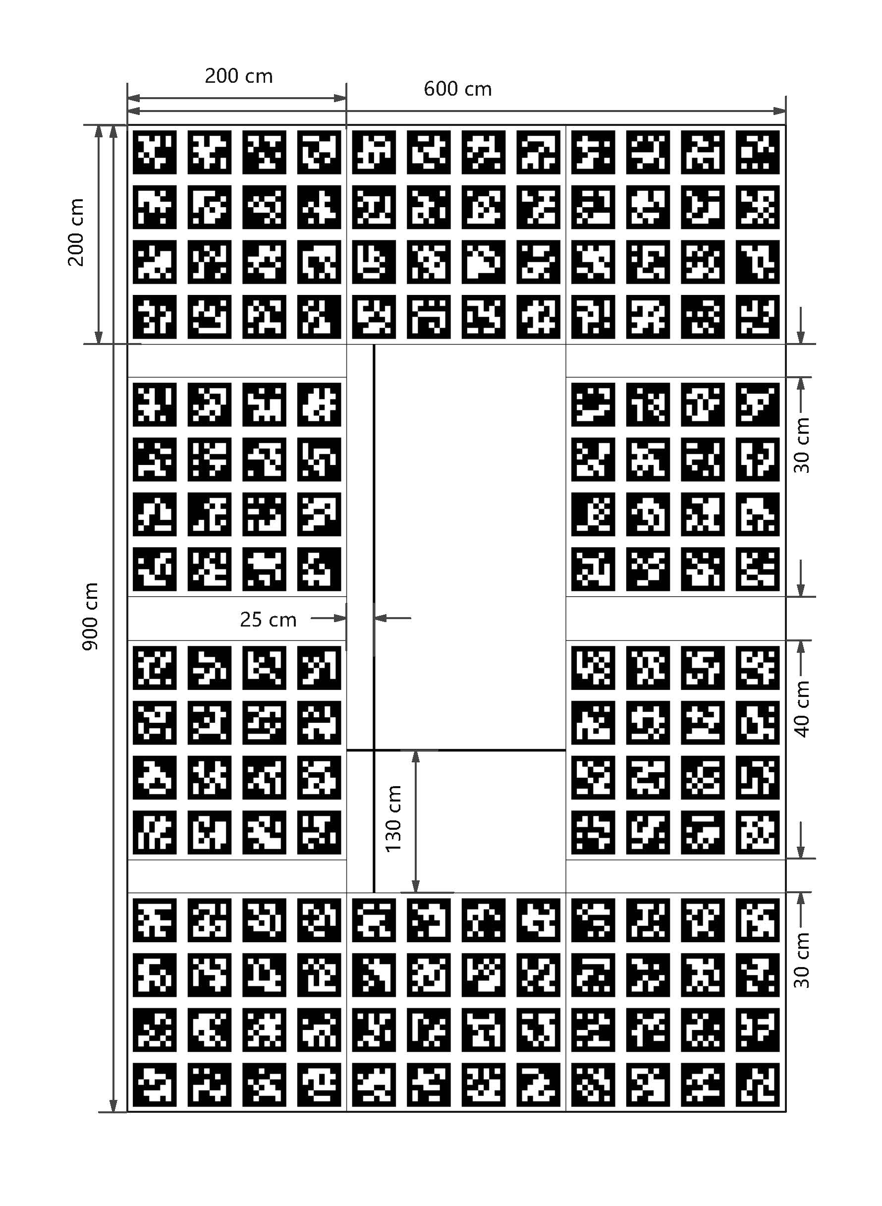
Given that the four surround view cameras are fixed around the vehicle and the IMU is installed at the rear axle center, it is not feasible to effectively excite this visual-inertial system along three axes. After extensive research, a camera-to-vehicle extrinsic calibration scheme based on the AprilTag ground calibration mat was chosen.
For the extrinsic calibration, the vehicle is parked in the blank area at the center of the calibration mat, with the left rear wheel positioned at the cross intersection, and the left front and right rear wheels aligned with the vertical and horizontal lines, respectively.
To further ensure the accuracy and robustness of AprilTag detection and localization, the Bundle Calibration mode is used. This mode calculates the common bundle pose for a group of tags. Based on the selected AprilTag codes and calibration mat size, the AprilTag configuration file ./src/apriltag_ros/apriltag_ros/config/tags.yaml is edited.
3.2 Camera-to-Vehicle Extrinsic Calibration
The camera-to-vehicle extrinsic calibration code can be found in avm_calibration.
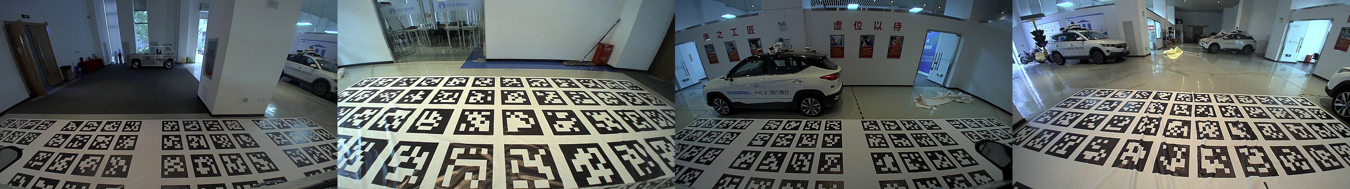
Once the vehicle is correctly positioned on the calibration mat, extrinsic calibration images can be captured, as shown in Figures 3.2.1 to 3.2.4. The captured calibration images are placed in the project data directory (./data), organized similarly to the intrinsic calibration. Next, a file named img.txt is created, listing all the calibration image filenames.
# ./data/img.txt
img1.jpg
img2.jpg
img3.jpg
...
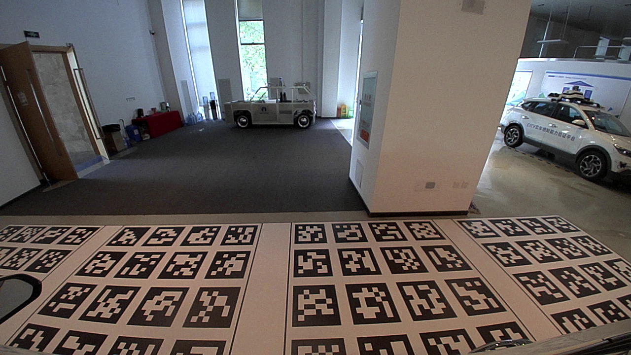
Figure 3.2.1 Extrinsic calibration image for the right fisheye camera
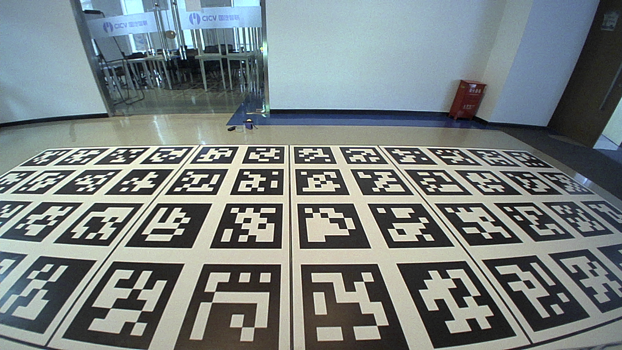
Figure 3.2.2 Extrinsic calibration image for the front fisheye camera
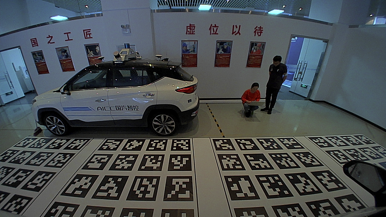
Figure 3.2.3 Extrinsic calibration image for the left fisheye camera
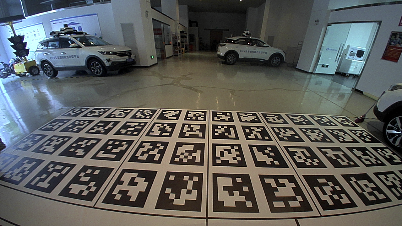
Figure 3.2.4 Extrinsic calibration image for the rear fisheye camera
After organizing the captured calibration images in the aforementioned manner, run the image_to_msg node to publish the calibration images. The topics are /cv_camera_${camera}/image_raw and /cv_camera_${camera}/camera_info.
rosrun image_to_msg image_to_msg
Next, run the continuous_detection node to detect AprilTags and estimate their poses in the camera coordinate system.
roslaunch apriltag_ros continuous_detection.launch
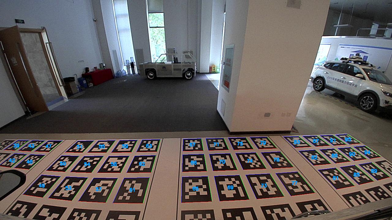
Figure 3.2.5 AprilTag detection result for the right fisheye camera
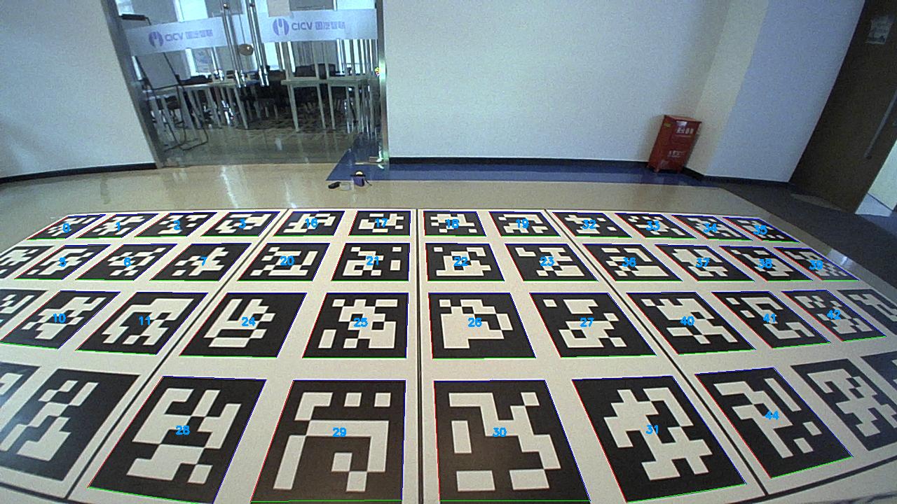
Figure 3.2.6 AprilTag detection result for the front fisheye camera
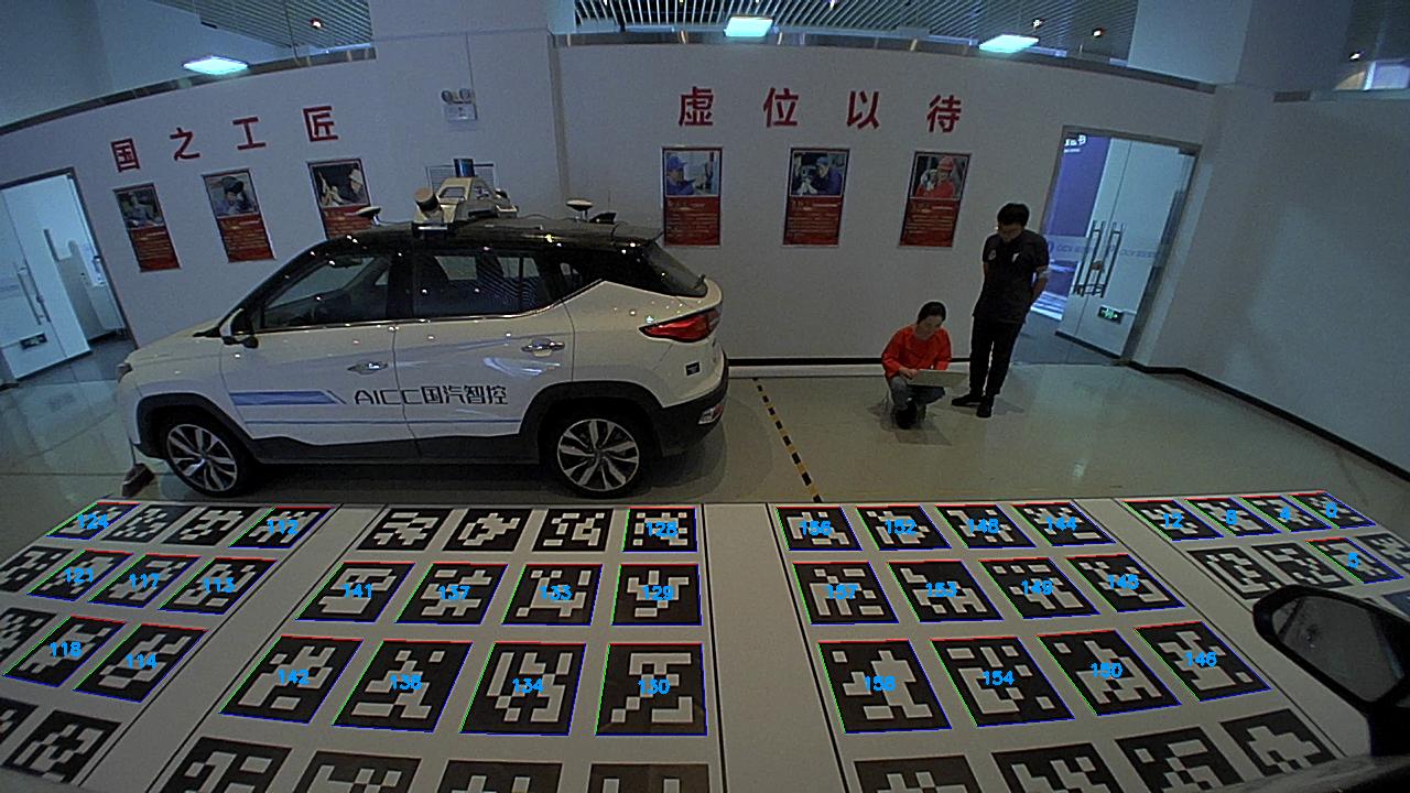
Figure 3.2.7 AprilTag detection result for the left fisheye camera
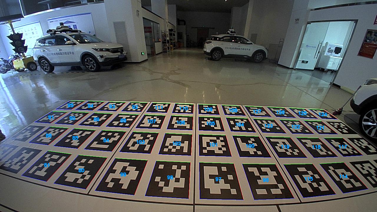
Figure 3.2.8 AprilTag detection result for the rear fisheye camera
After ensuring proper AprilTag detection, run the localize node to integrate the localization results. Using the known transformation relationships between the tag bundle coordinate systems, the positions and orientations of the four surround view cameras relative to the cross intersection of the calibration mat (i.e., the center of the right rear wheel of the vehicle) are obtained and saved as the calib_extrinsic.yaml file.
# --------------------
# calib_extrinsic.yaml
# --------------------

frame_id: bundle_all
pose_wheel_camera_right: [0.85776595366551245, -1.3297249786546665, 1.70759463357486, -0.0037461082991290216, 0.012662183501864755, 0.85994211722375269, -0.51022072753496184]
pose_wheel_camera_front: [3.4728684909554812, -0.73169474983827887, 0.92578770800106336, 0.32955744240001894, -0.6233047217244837, 0.62466249399100093, -0.33567824569915911]
pose_wheel_camera_left: [0.84327463846461403, -0.22055318829518084, 1.7250547956887143, 0.52043734275821096, -0.8538966208432508, 0.0017313909010818068, 0.0015923130339794826]
pose_wheel_camera_rear: [-0.77796316183817105, -0.77092134403012258, 1.2366664981364999, -0.34863975481374709, 0.60202525692481423, 0.62964173407872581, -0.34578490148408281]
3.3 Extrinsic Calibration Results
Let \(\boldsymbol t_{wc}\) and \(\boldsymbol q_{wc}\) represent the translation and rotation transformations of the camera coordinate system relative to the cross intersection of the calibration mat (i.e., the rear wheel of the vehicle), respectively. The four surround view cameras are identified with subscripts.
The extrinsic calibration results are recorded as follows:
\[\boldsymbol t_{wc\_right}= \begin{bmatrix} 0.857 & -1.329 & 1.707 \end{bmatrix}^T\] \[\boldsymbol q_{wc\_right}= \begin{bmatrix} -0.003 & 0.012 & 0.859 & -0.510 \end{bmatrix}^T\] \[\boldsymbol t_{wc\_front}= \begin{bmatrix} 3.472 & -0.731 & 0.925 \end{bmatrix}^T\] \[\boldsymbol q_{wc\_front}= \begin{bmatrix} 0.329 & -0.623 & 0.624 & -0.335 \end{bmatrix}^T\] \[\boldsymbol t_{wc\_left}= \begin{bmatrix} 0.843 & -0.220 & 1.725 \end{bmatrix}^T\] \[\boldsymbol q_{wc\_left}= \begin{bmatrix} 0.520 & -0.853 & 0.001 & 0.001 \end{bmatrix}^T\] \[\boldsymbol t_{wc\_rear}= \begin{bmatrix} -0.778 & -0.771 & 1.236 \end{bmatrix}^T\] \[\boldsymbol q_{wc\_rear}= \begin{bmatrix} -0.348 & 0.602 & 0.629 & -0.345 \end{bmatrix}^T\]3.4 Evaluation of Extrinsic Calibration Results
Using the extrinsic calibration results, the relative poses between the tag bundles on the ground calibration mat are calculated and compared with the ground truth for a simple evaluation of the extrinsic calibration results, as shown in the table below.
| RMSE_position | RMSE_orientation | NEES_position | |
|---|---|---|---|
| camera_right | 0.013m | 0.25° | 0.23% |
| camera_front | 0.010m | 0.28° | 0.12% |
| camera_left | 0.022m | 0.50° | 0.66% |
| camera_rear | 0.007m | 0.17° | 0.19% |
4. Related Links
code: