Tolles-Lawson Model for Aeromagnetic Compensation
Published:
Tolles-Lawson Model for Aeromagnetic Compensation.
Derivation and Extensions of the Tolles-Lawson Model for Aeromagnetic Compensation
link:
The basic idea of the Tolles-Lawson model [9] is to use magnetic measurements from a vector magnetometer to calibrate a scalar magnetometer, the latter of which is used for navigation. This model provides a means for removing a corrupting aircraft magnetic field from a scalar total magnetic field measurement, yielding the Earth magnetic field used for navigation.
An airborne vector magnetometer measures the vector sum of two primary magnetic fields,
\[\vec{B}_t=\vec{B}_e+\vec{B}_a\]After some mathematical manipulations, a linear relationship can be obtained.
\[|\vec{B}_e|\approx|\vec{B}_t|-\vec{B}_t\cdot\hat{B}_t\]Note that the scalar form is obtained because the scalar earth magnetic measurements are required during the navigation.
Tolles and Lawson assumed that the aircraft field is comprised of permanent, induced, and eddy current magnetic moments.
\[\vec{B}_a=\vec{B}_{perm}+\vec{B}_{ind}+\vec{B}_{eddy}\]It is further reduced to the simplified form of
\[\vec{B}_a=\boldsymbol{a}+\boldsymbol{b}\vec{B}_t+\boldsymbol{c}\dot{\vec{B}}_t\]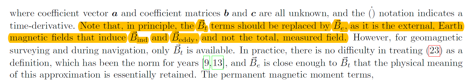
As can be seen in “Derivation and Extensions of the Tolles-Lawson Model for Aeromagnetic Compensation”, strictly speaking, it is the earth field that induces the induced and eddy terms, rather than the measured field.
An approximation is made here in the derivation of TL-model.


The “trick” is to use a bandpass filter, typically a Butterworth infinite impulse response filter is chosen.
The passband frequency range for the bandpass filter is carefully selected in order to remove nearly all of the earth field while keeping much of the aircraft field by setting to the periodicity of the pitch, roll, and yaw maneuvers.
The calibration flight is performed at a high altitude over a region with a small magnetic gradient to reduce the uncertainty imparted by the earth field.
However, when solving the TL-model in vector form, the earth field represented in the aircraft coordinate system changes with the maneuvers of the aircraft.
As a result, the “trick” is not effective anymore.
When a high-quality map is available for calibration, a bandpass filter is not necessary, and calibration flights should occur at lower altitudes for map-based aeromagnetic calibration and compensation.
As is claimed in “Derivation and Extensions of the Tolles-Lawson Model for Aeromagnetic Compensation”, the earth field can be obtained by the magnetic map.
In our project, it can also be measured by the magnetometer that is installed outside of the cabin (i.e., the groundtruth used in the training of the network).
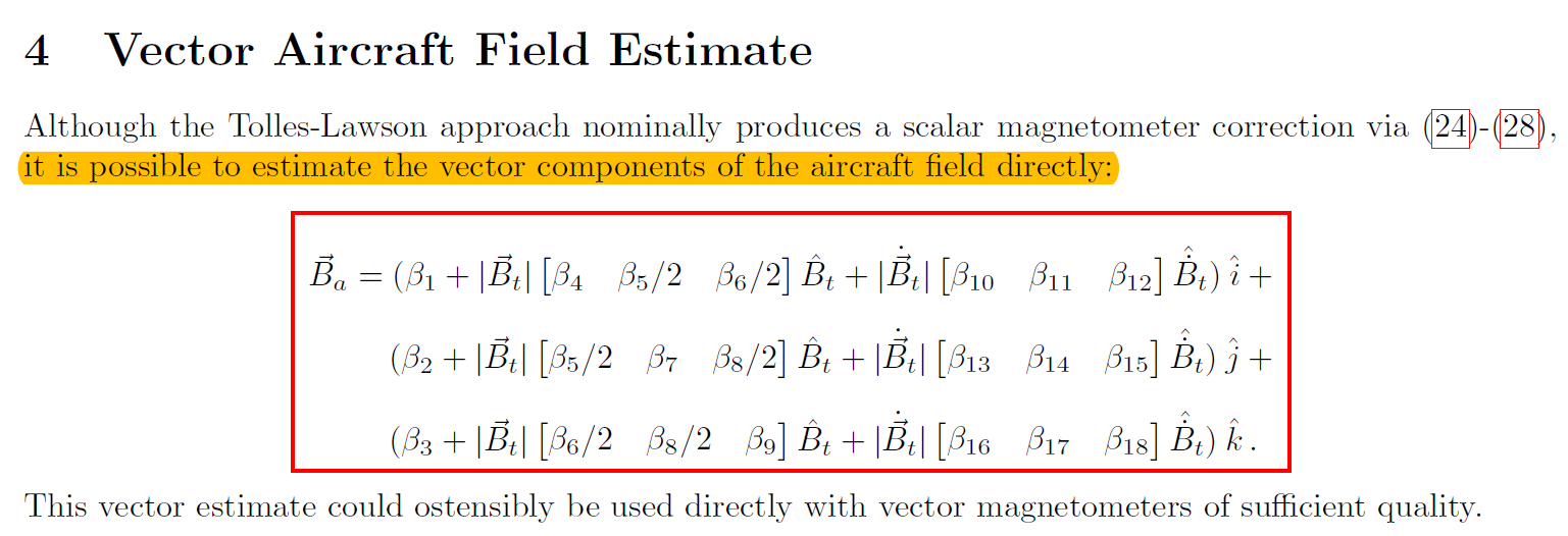
I’ve never seen that the vector field can be solved this way…
Magnetic Navigation on an F-16 Aircraft Using Online Calibration
Magnetic anomaly navigation has recently been flight test proven on an F-16 aircraft. The corrupting magnetic environment on this operational platform is 2–3 orders of magnitude larger than previous flight-tests on geo-survey aircraft, while also displaying stochastic drift. The difficult magnetic environment of the platform necessitated a combination of batch and online calibration to obtain accurate navigation solutions.
When calibrating a scalar sensor, all magnetic fields in the body-frame of the aircraft create corrupting fields which are coupled to aircraft attitude.
Discussed in this article are two major types of “truthing” to drive the calibration of the magnetometer measurements: map-based calibration and map-less calibration.
The first method, map-based calibration, is less common in the literature, but more intuitive. This calibration method flies through a high-quality magnetic anomaly map (with GPS) and calibrates the system measurements such that they most closely match the magnetic anomaly map. This method requires highly accurate magnetic anomaly maps but can produce the best results given the navigation system is also using this map to navigate. This method cannot produce calibration errors smaller than the errors which exist in the magnetic map-products being used.
Map-less calibration is more practical in many situations and relies on the idea of a “disturbance field.” A disturbance field takes advantage of the physics of the slowly varying earth magnetic field and band-pass filters the scalar magnetic data such that no earth field remains in the signal. Note this method also eliminates some of the aircraft fields, however, a mathematical model which fits the band-pass filtered data can then be expanded to predict magnetic field effects across the entire frequency spectrum. This method is more brittle than map-based calibration and suffers from observability issues but has the obvious benefit of not requiring a map.