Orientation Estimation for Triaxial Magnetometer in Non-Uniform Magnetic Field Environments
Date:
Background
In the Tolles-Lawson model-based aeromagnetic compensation system, it is mentioned that external vector magnetometers are installed outside the cabin to synchronously obtain geomagnetic field information, thereby completing the calibration of vector disturbance magnetic fields. Additionally, in magnetic compensation solutions based on deep learning methods, acquiring true value information is also an urgent problem to be solved.
This proposal presents an orientation estimation scheme for triaxial magnetometers in non-uniform magnetic field environments. It utilizes high-precision turntables and devices like spirit levels to achieve coordinate alignment for vector magnetometers.
Orientation Estimation for Triaxial Magnetometers
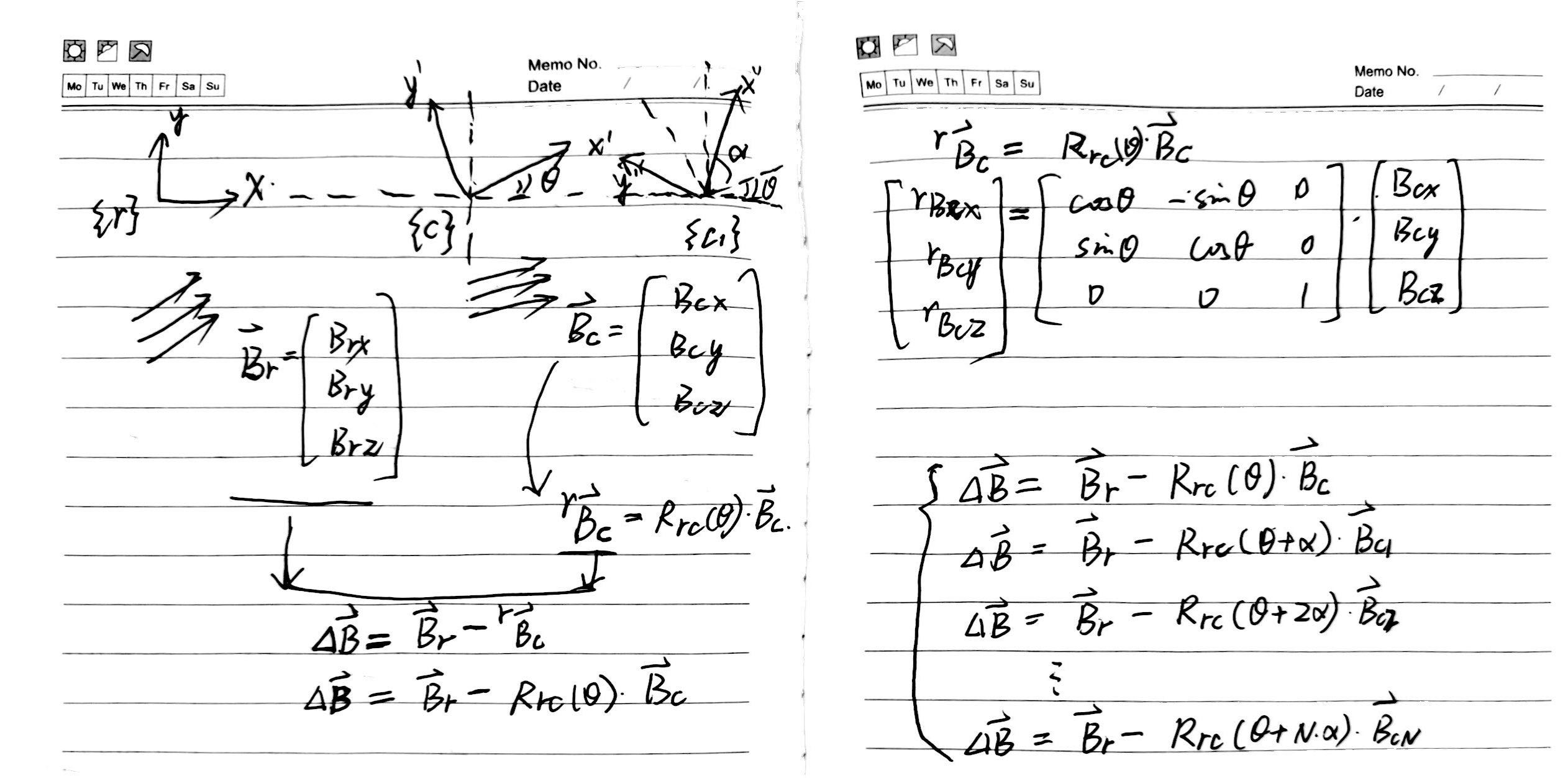
Assuming two triaxial magnetometers are in magnetic fields of different magnitudes and directions, both constant and unaffected by time or sensor rotation.
Sensor 1 (with high-precision rotating mechanism) and Sensor 2 are both horizontally leveled simultaneously for convenience, aligning the \(Z\) axis parallel to the direction of gravity, as illustrated in the diagram below.
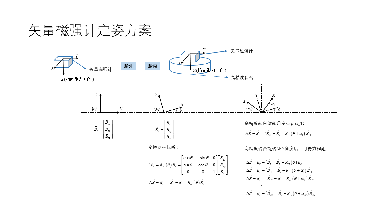
The measurement results of Sensor 2 for the magnetic field are
\[\vec{B}_r= \begin{bmatrix} B_{rx} \\ B_{ry} \\ B_{rz} \\ \end{bmatrix}\]where symbol \(r\) denotes the body coordinate system of Sensor 2.
Fixing the high-precision turntable below Sensor 1, the measurement results for the magnetic field are obtained as
\[\vec{B}_c= \begin{bmatrix} B_{cx} \\ B_{cy} \\ B_{cz} \\ \end{bmatrix}\]Similarly, symbol \(c\) represents the body coordinate system of Sensor 1.
Transforming \(\vec{B}_c\) to the coordinate system \(r\), we obtain
\[{}^r\vec{B}_c=R_{rc}(\theta)\vec{B}_c= \begin{bmatrix} \cos\theta & -\sin\theta & 0 \\ \sin\theta & \cos\theta & 0 \\ 0 & 0 & 1 \end{bmatrix} \begin{bmatrix} B_{cx} \\ B_{cy} \\ B_{cz} \\ \end{bmatrix}\]Thus, the difference of magnetic measurements represented in the coordinate system \(r\) is
\[\Delta\vec{B}=\vec{B}_r-{}^r\vec{B}_c =\vec{B}_r-R_{rc}(\theta)\vec{B}_c \tag{1}\]where the difference of magnetic measurements \(\Delta\vec{B}\) and the angle difference \(\theta\) between the two magnetometers are the variables to be solved. Thus, Equation (1) provides a constraint for this parameter identification problem.
Using the high-precision turntable, after rotating Sensor 1 by an angle \(\alpha_1\), its coordinate system at this time is denoted as \(c1\), providing the second constraint condition.
\[\Delta\vec{B}=\vec{B}_r-{}^r\vec{B}_{c1} =\vec{B}_r-R_{rc}(\theta+\alpha_1)\vec{B}_{c1} \tag{2}\]Similarly, after rotating Sensor 1 by \(N\) angles and combining all the constraints together, we obtain
\[\begin{aligned} &\Delta\vec{B}=\vec{B}_r-{}^r\vec{B}_c =\vec{B}_r-R_{rc}(\theta)\vec{B}_c \\ &\Delta\vec{B}=\vec{B}_r-{}^r\vec{B}_{c1} =\vec{B}_r-R_{rc}(\theta+\alpha_1)\vec{B}_{c1}\\ &\Delta\vec{B}=\vec{B}_r-{}^r\vec{B}_{c2} =\vec{B}_r-R_{rc}(\theta+\alpha_2)\vec{B}_{c2}\\ &\quad\quad\quad \vdots \\ &\Delta\vec{B}=\vec{B}_r-{}^r\vec{B}_{cN} =\vec{B}_r-R_{rc}(\theta+\alpha_N)\vec{B}_{cN}\\ \end{aligned}\]Thus, using nonlinear least squares or similar identification methods, we can solve for the unknown parameters \(\Delta\vec{B}\) and \(\theta\), addressing the orientation problem of two triaxial magnetometers in a non-uniform magnetic field.