Patents by Walter E Tolles relating Tolles-Lawson Model
Published:
Two Patents relating Tolles-Lawson Model.
Compensation of induced magnetic fields
link: Compensation of induced magnetic fields (US2834939A, Walter E Tolles)
I read this patent for the derivation of the eq.(3) in Patent US2692970A.
This invention relates to compensation systems, and more particularly to methods of and means for compensating the induced magnetic fields of aircraft.
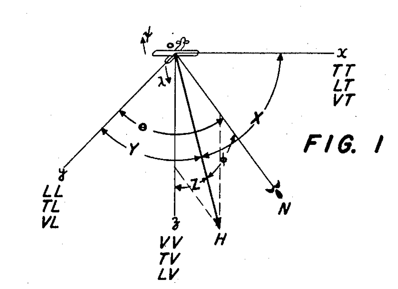
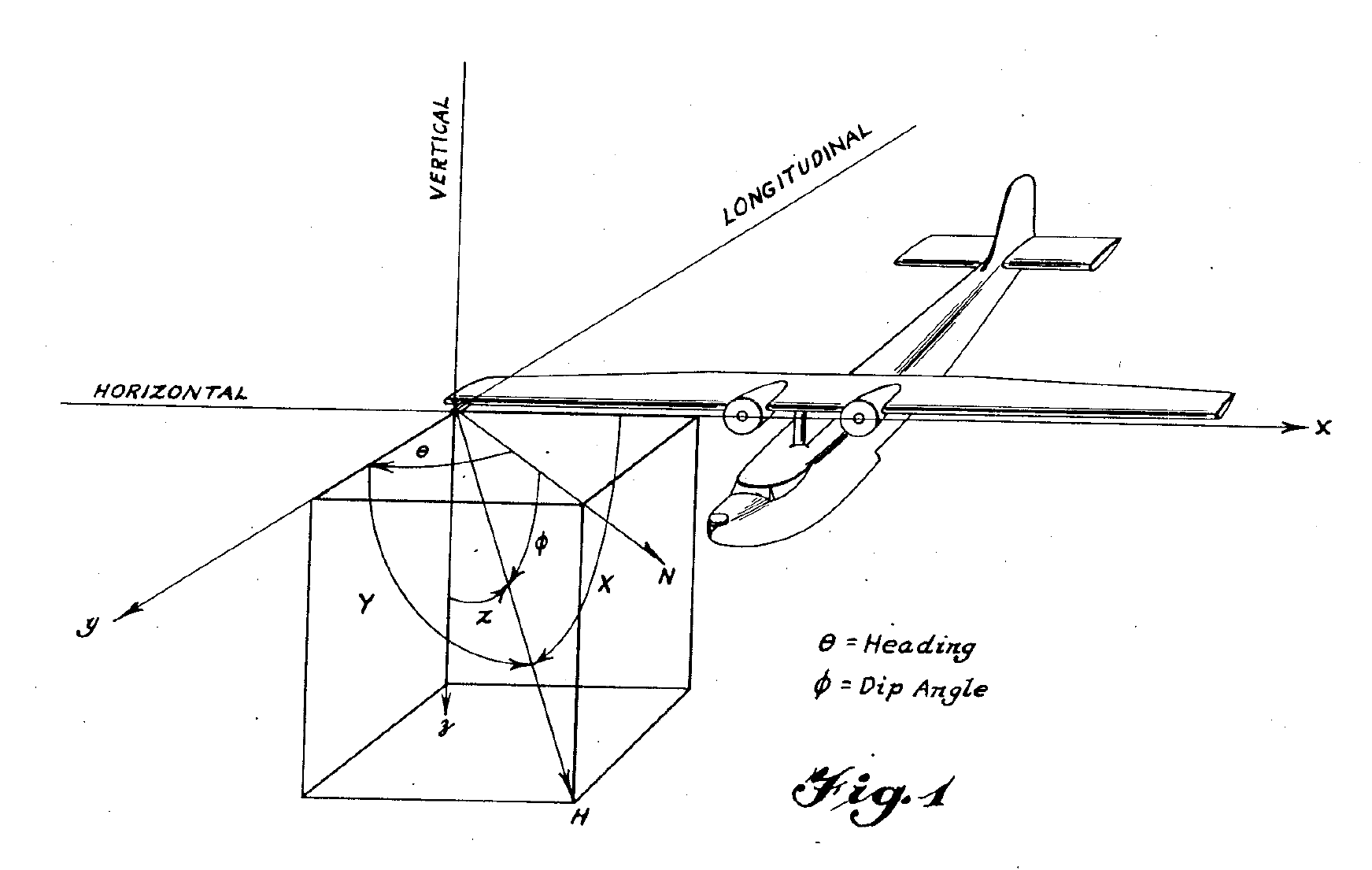
The total induced magnetic field due to all soft magnetic parts of an aircraft structure may be reproduced by a system of three suitable virtual bars oriented in chosen directions in respect to the aircraft. Referring to Fig. 1, the aircraft is shown at the origin of a coordinate system in which the x, y and z axes are parallel respectively to the transverse, longitudinal and vertical axes of the aircraft. The three virtual bars mentioned above may be chosen in such fashion that one of them is parallel to each of these reference axes, the bar parallel to the x axis. being designated the transverse bar, that parallel to they axis being designated the longitudinal bar, and that par allel to the z axis being designated the vertical bar.
Accordingly, a double-letter system is used in which the first letter indicates the orientation of the bar causing the field component and the second letter indicates the direction of the component caused thereby. Thus the transverse bar which produces components in the transverse, longitudinal and vertical directions may result in components designated as TT, TL and TV. Similarly, there will be other components designated LL, LV, LT, VV, VL and VT. The components acting along each of the three reference axes have been indicated in Fig. 1.
For better understanding, I rewrite the eq.(1) in the patent as
\[\begin{aligned} \vec{H}_I&=\vec{i}(TT\cdot H\cos X+LT\cdot H\cos Y+VT\cdot H\cos Z) \\ &+\vec{j}(TL\cdot H\cos X+LL\cdot H\cos Y+VL\cdot H\cos Z) \\ &+\vec{k}(TV\cdot H\cos X+LV\cdot H\cos Y+VV\cdot H\cos Z) \end{aligned}\]where \(H\cos Y\) represents the projection of the earth magnetic field onto the x axis (transverse virtual bar), and \(TL\) is the coefficient of the induced magnetic field caused by the transverse component (1st letter) on the longitudinal direction (2nd letter).
\[H_{ID}= \begin{bmatrix} \cos X & \cos Y & \cos Z \end{bmatrix} \vec{H}_I\]Of the total induced field, only the component in the direction of the earth’s magnetic field affects the operation of a magnetometer arranged to measure components in the direction of the earth’s magnetic field. Resolving the field of Equation 1 in the direction of the earth's magnetic field results in an expression of the following form:
Expanding the above equation yields eq.(3) in Patent US2692970A.
Each term on the right-hand side of Equation 2 represents a component of induced field acting in the direction of the earth’s magnetic field which must be compensated if satisfactory operation of the magnetometer is to be obtained. In each of these terms, the double-letter co efficient (TT, VV, etc.) is a constant which is determined by the structural characteristics of the aircraft and by which the magnitude of the earth’s field must be multiplied to give the magnitude of the particular component, while the trigonometric argument in each case indicates the manner in which this amplitude varies as the aircraft maneuvers.
Compensation of aircraft magnetic fields
link: Compensation of aircraft magnetic fields (US2692970A, Walter E Tolles)
This invention relates to compensation of magnetic fields, and more particularly to the compensation of the effect in a given direction of the magnetic field of an aircraft due to all sources.
Considering the nature of the total magnetic field of an aircraft, it will be seen that this magnetic field may be due to contributions from several sources which produce magnetic field components of different types. Ferromagnetic elements in the aircraft structure having high retentivities become permanently magnetized and each of then produces a magnetic field. The sum of all of these permanent magnetic field com ponents is known as the “perm” magnetic field of the aircraft and is constant in magnitude and in direction in respect to the aircraft.
"Soft" ferromagnetic elements in the aircraft structure are magnetized through induction by the earth's magnetic field and each set up an induced magnetic field which varies in magnitude and direction with the geographical location of the aircraft and its attitude in space. The total induced imagnetic field of the aircraft is the sum of the induced fields of all “soft” ferromagnetic structural elements, and its contribution to the total magnetic field of the aircraft is accordingly complex in nature.
Additional contributions to the total magnetic field of the aircraft are produced by eddy currents which are induced in sheet conductors, as for example in the metal skin forming portions of the aircraft, or in metallic loops, such as control cable assenblies, whenever the attitude of the aircraft changes. The total eddy-current magnetic field contribution will thus be understood to depend in a complex way upon the geographical location of the aircraft, upon its attitude in space, and upon the rate of change of the attitude of the aircraft.
When the measuring instrument installed in the aircraft is a portable magnetometer of the type including a magnetometer element and arranged to be continuously oriented in the direction of the earth's magnetic field and to measure magnetic field components in that direction only, special problems are encountered. Since the magnetornetter element is so oriented as to maintain a substantially constant attitude in space, the portion of the total magnetic field of the aircraft affecting the output of the magnetometer will also vary with the attitude of the aircraft in space.
Note that the original Tolles-lawson is not applied on a strapdown system.
It is an object of the present invention to provide means whereby the various magnetic fields contributing to the total magnetic field of an aircraft may, each in the presence of the other, be compensated for their effect on a magnetometer arranged to measure magnetic fields in the direction of the earth's magnetic field.
Accordingly, there is provided a method of compensating the magnetic field of an aircraft to facilitate operation of a magnetometer mounted therein for measuring magnetic field components in a chosen direction which includes choosing a set of reference axes in respect to the aircraft; resolving the perm, induced, and eddy-current imagnetic fields of the aircraft into components along these axes; choosing a series of maneuvers such that the output of the magnetometer is in each case due to identifiable components of the perm and induced magnetic fields, and to at least one eddy-current magnetic field component; performing each maneuver of the series in turn, temporarily eliminating the effect of the perm and induced magnetic field components on the magnetometer for each maneuver, and compensating the eddy-current magnetic field conponent thus identified; thereafter performing a second set of maneuvers such that the output of the magnetometer is due in the case of each maneuver to identifiable components of the perm and induced magnetic fields; and compensating each of these components as identified.
Referring to Fig. 1, a set of orthogonal reference axes x, y and z is chosen in respect to the aircraft. Conveniently, the reference system including these axes has its origin at the location of the magnetometer element and is so chosen that the x, y and z axes are parallel respectively to the transverse, longitudinal and vertical axes of the aircraft. Angles X, Y and Z are direction angles indicating respectively the orientation of the x, y and z axes in respect to the earth’s magnetic Vector designated in the drawing by the arrow marked H.
\[\vec{H}_p=T\vec{i}+L\vec{j}+V\vec{k}\]The total magnetic field due to all permanently magnetized structures in the aircraft may be resolved into three components T, L and V, parallel respectively to the x, y and z axes.
\[H_{pd}=T\cos X+L\cos Y+V\cos Z\]Since the magnetometer is arranged to measure only magnetic field components in the direction of the earth’s magnetic field, the total perm magnetic field \(\vec{H}p\) may be resolved in the direction of the earth’s magnetic vector H. The effective perm magnetic field \(H{pd}\) is then
\[\begin{aligned} H_{ip}=&H[TT\cos^2X+(LT+TL)\cos X\cos Y \\ &+LL\cos^2Y+(VT+TV)\cos X\cos Z \\ &+VV\cos^2Z+(LV+VL)\cos Y\cos Z] \end{aligned} \tag{3}\]The induced magnetic field of an aircraft effective in the direction of the earth’s magnetic field is given by the following expression.